- Home
- Services
- Products
- Learning Lab
- Tools
- Contact

RURAL WATER DISTRIBUTION CUSTOMER KIOSKS
BACKGROUND: We were approached by a company that ran a rural water distribution system. In this town there were many households without running water and the cost of installing a well was too expensive or not practical. Their business provided customers without city provided running water a place to pay cash and fill bulk water containers. The customer wanted to provide a system for his customers that would give them the ability to add cash to their account and then use that credit to buy water as needed. The caveat was they had an Allen-Bradley based PLC system which monitored the cash installed and dispensed the water based on the credit.
SOLUTION: Overlay a Linux based server that would keep record of customer accounts and credit through a MySQL database. The customer would interface with the server through an HID key fob for security and a keypad to enter the number of gallons to dispense. The server would direct the PLC to how many gallons to dispense and then debit the account and record the transaction. The customer could also add cash directly at the Kiosk to be added to their account. A webpage was created for operators and accounting to access customer accounts to add credit as well as monitor customer accounts.
SYSTEM: Used the Linux operating system as the server, MySQL database, PHP and HTML for user access and RaspberryPI as a serial port gateway in the TCP/IP communications.
RESULT: The cashless system is being used by over 50% of their customers which has saved the owner a lot of manpower spent counting coins and bills. They can simply run a report now which accounts for the money spent and gallons of water dispensed each day. An unexpected benefit is they can now see which stations are being utilized the most and can perform preventative maintenance rather than waiting for failures.
Over 100k+ transactions later both the customer and their customer’s are extremely happy with the solution.

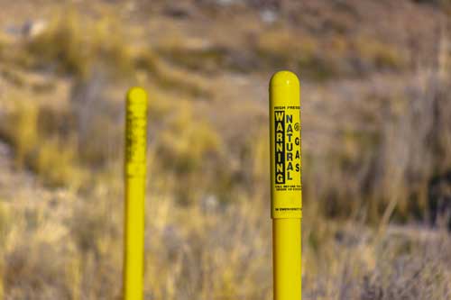
GAS UTILITY PANELS AND SCADA
BACKGROUND:
SOLUTION:
SYSTEM:
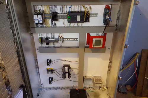
Provided UL508a listed panels for the remote stations which contained the PLC and battery backup-up. With the battery back-up the panel could run for 24 hours without utility power continuing to provide reads and notify of power loss situation.
RESULT:During one summer building season the system was able to notify operator’s that a gas line had suddenly lost pressure. They were able to respond quickly and found that a backhoe operator had punctured one of the lines. The gas utility management was happy to have the ability to track down the problem very quickly.
Now over 3 years later, the system has run continuously without any IT supervision. Server uptime has been 100% and the cellular polling system has recorded only a single short outage. The customer has been very happy with the hands-off system that was provided.
CONTAMINATED GROUNDWATER MONITORING AND PUMP SYSTEM
BACKGROUND:
SOLUTION:
SYSTEM:
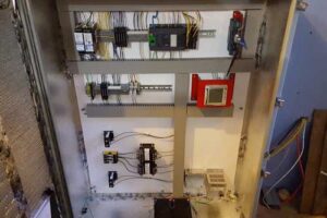
The remote panels were backed up by batteries to notify the master in case of power loss.
VTScada was used for the monitor and control interface for the system. This would give the dispatchers continual feedback as to the status of the system. It also provided a means by which to send email and texts in the event of an alarm condition. An autodialer system by Sensaphone was provided as a second means of notifying via phone lines if an alarm went unnoticed for a preset interval.
RESULT: The system proved to be a great success and allowed the plant operator to utilize their operator’s to perform other tasks rather than continually checking the status of the groundwater pumps.
 BREAKER FAIL LOGIC FOR SEL 387E RELAYS
BACKGROUND: Breaker fail logic is added to a SEL 387E relay. When the primary beaker is commanded to open but fails, the secondary back-up breaker needs to open clearing the fault. Breaker fail logic is needed in many cases. Breaker failures can happen due to flash over or trip coil failure.
Breaker fail circuits typically surround the primary breaker circuits and encompass a larger equipment outage.
SOLUTION: When the primary breaker is commanded to open with a trip signal, a breaker fail timer is started. The timer setting is typically double the time it takes for the standard trip to occur. The timer value is in the order of 15 cycles. If current in the primary breaker circuit goes below a low threshold value, the timer is reset, and no breaker fail is initiated. If the current in the primary breaker continues due to a breaker pole not opening or a flash over event, the breaker fail timer times out and opens the secondary breaker circuit.
SYSTEM: Standard internal relay timers and status variables are used to implement the breaker fail logic.
BF-TIMER-INPUT=(TRIP OR BF-TIMER-INPUT) AND (PRIMARY BREAKER AMPS STILL FLOWING);
BF-TIMER-OUT = BF-TIMER-INPUT FOR 15 CYCLES; BF-TRIP=BF-TIMER-OUT;
RESULT: Testing of the breaker fail logic involves blocking the primary breaker open signal so that current flows after the TRIP signal is present. Testing shows this logic works as designed. Typically a 15 cycle timer is used. Longer timer values can be used to increase security but will potentially cause more fault damage. The TRIP signal forces the BF-TIMER-INPUT to logical 1, BF-TIMER-INPUT then latches itself logical 1 until PRIMARY BREAKER AMPS STILL FLOWING goes to logical 0. If BF-TIMER-INPUT continues at logical 1 for greater than 15 cycles, BF-TRIP is forced to logical 1 and trips open the secondary breaker fail circuit.

PID SYSTEM MODEL FOR CLOSED LOOP SIMULATIONS WITH PIDSIM
BACKGROUND: PID loop tuning can be difficult on operating systems. Critical systems that can damage equipment on instability need special care for PID loop tuning. Tuning these critical systems off line with PIDSim increases the probability for success and creates significant peace of mind in the field.
SOLUTION: IEI’s PIDSim implements the PID function block and the first or second order system model. This complete system model is used to tune the PID controller off line for significant time saving in the field on PID loop start-up.
Gather the plant system model step response data, enter the system step response data into PIDSim, run the simulator and use standard methods to tune the loop. No worries about system instability.
SYSTEM: PIDSim uses the standard ISA PID controller model and a second order system plant model. Step response data is entered into the plant system model to achieve a simulated step response close to that of the actual plant. The PIDSim PID loop controller is then adjusted to control the plant model as if it was actually controlling the real plant.
RESULT: PIDSim gives piece of mind when implementing new PID loop controller constants. PIDSim has been used successfully in many applications including water pressure, air flow, air pressure and temperature control systems. PID constants can be optimized without the fear of instability on an operating system.
 GROUNDED WYE DELTA TRANSFORMER POWER SYSTEM DISTRIBUTION MODELING WITH ETAP
BACKGROUND: Power systems are easily modeled with ETAP power system modeling software. A grounded Wye Primary and Delta secondary transformer can cause significant coordination problems during a Wye side ground fault. Nuisance tripping on un-involved radial feeders occur. Voltage imbalances in the grounded Wye side during the ground fault cause zero sequence currents to flow in the transformer Delta side. This in turn induces zero sequence current back feeding into the Wye side contributing to the ground fault currents.
SOLUTION: System parameters are gathered and the one line diagram is modeled in ETAP software. Ground faults are then simulated to verify the magnitude of the problem. Over-current devices are then coordinated. The typical solution is to un-ground the Wye side transformer preventing zero sequence current from flowing. An alternate solution is to implement directional 21 element over current protection.
SYSTEM: Options were evaluated using ETAP software. A direction 21 element relay was implemented to prove the application. Ultimately, the transformer Wye neutral was un-grouned preventing zero sequence current from flowing. This system was chosen for simplicity.
RESULT: Several ground faults have occurred since the transformer Wye neutral un-grounding. No nuisance tripping has occurred. ETAP software accurately simulated the power system ground faults.
PRINT/DOWNLOAD THIS
- Home
- Services
- Products
- Learning Lab
- Tools
- Contact


